Beginners
car project
 |
 |
About:
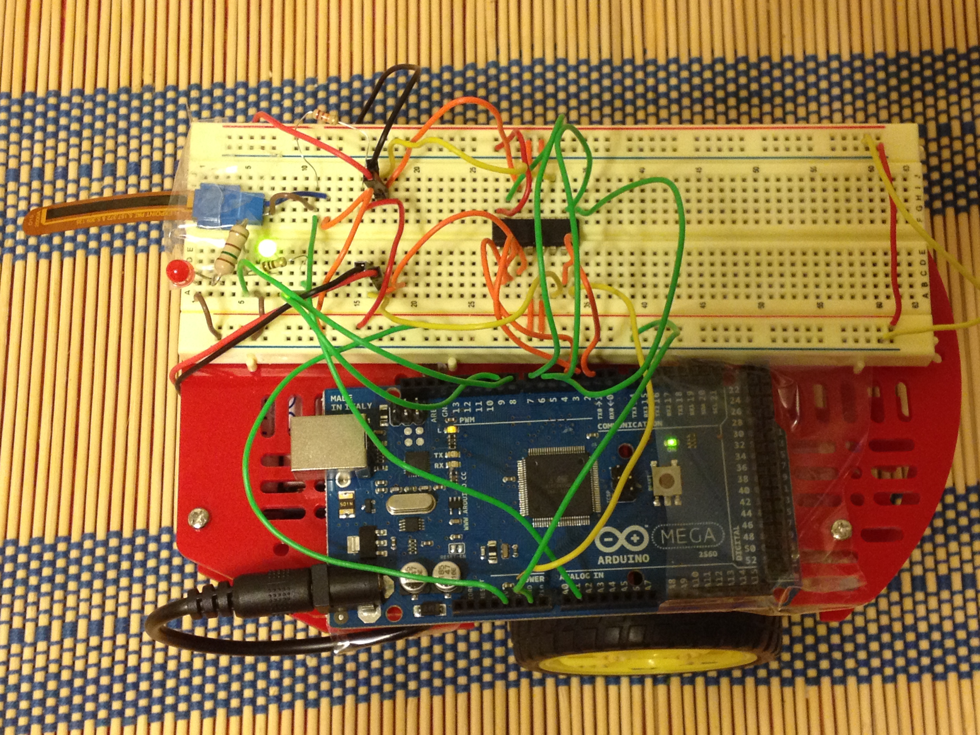
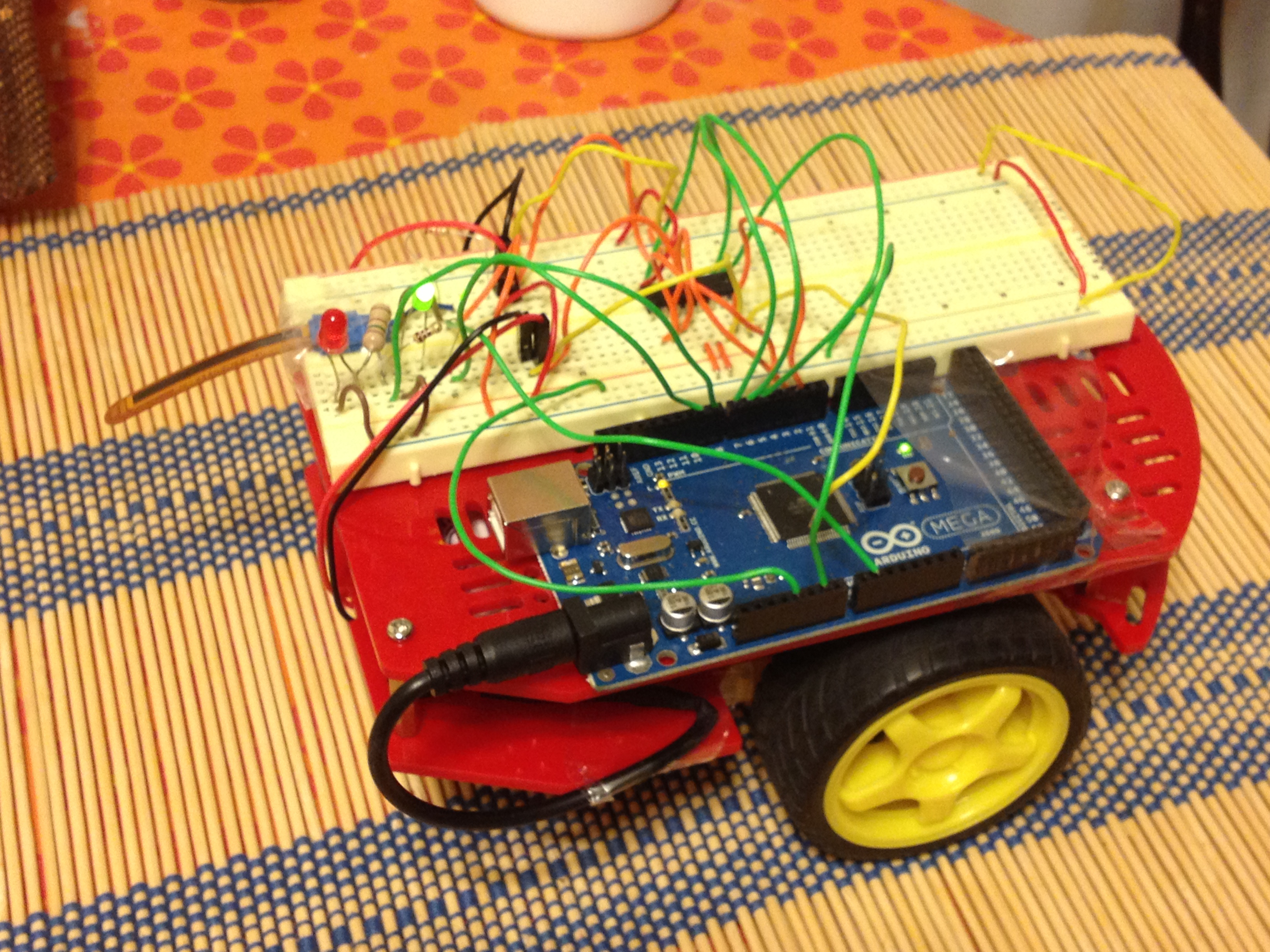
A wheeled robot that moves around and uses a flex (bend) sensor to detect collision. Videos: low(0.5 MB) and high (4MB)
Things needed
How to build
Code:
my_car_project.ino (.ino is arduino file extension. This can also be opened with text editor)
A tip:
Understand, interface and write code each component separately before putting it all together.
Ideas that failed
I was looking for various sensing options. Some failed ideas
Updated: 15 Nov 2012.
A wheeled robot that moves around and uses a flex (bend) sensor to detect collision. Videos: low(0.5 MB) and high (4MB)
Things needed
- Magician chassis (comes with 2 motors) - $15 (link) (cached)
- Arduino uno (for control) 2560 $59 (link)
- H-bridge motor driver (can be used to control 2 motors) SN754410 $2.35 (link)
- Flex sensor $8.00 (link) (cached)
- 20 kilo ohm resistor
- Solderless breadboard jumper wire kit $7 (search on radioshack.com) (cached)
- Breadboard (used 6" but smaller is better) $16.50 (link)
- Voltmeter (useful for debugging)
- 2 LEDs (1 Red for forward motion) and (1 Green for reverse motion) (useful for debugging)
- 2 Resistors of 100 ohm (for connecting the LEDs)
- 4 AA batteries (to power the motors and arduino)
- USB A to B cable (to program the arduino). These are used on printers and some external hard drives.
How to build
- Building the magician chassis. See the instructions that come with the chassis.
- Download arduino software and play with some examples before you start writing code for h-bridge and flex sensor. Link to Examples.
- Interfacing the h-bridges. See tutorial by Prof Winkler (link and cached file). You can extend this to power two motors. This will take 3 digital pins per motor on your arduino. 2 for direction control and 1 for speed control.
- Interfacing the flex sensor. The flex sensor is a variable resistor (like a pot). The resistance increases as the sensor is bent. Use a voltage divider circuit to interface the flex sensor. The flex sensor I used had a range of 5 - 30 kilo ohm. I used a 20 kilo-ohm external resistor in series with the sensor. This sensor takes 1 analog port on the arduino.
Code:
my_car_project.ino (.ino is arduino file extension. This can also be opened with text editor)
A tip:
Understand, interface and write code each component separately before putting it all together.
Ideas that failed
I was looking for various sensing options. Some failed ideas
- Infra Red (IR) sensor QRE1113 (analog). The idea here was to use a the IR sensor to do line detection. Here is the circuit I used to hook up the sensor (link and cached). My goal was to attach it to the chassis like this (link and cached file). I gave up on this idea because I did not have a suitable track to test it.
- Optical detector QRD1114. The idea was to use this sensor detect obstacles. Here is the circuit I used (see end of page and cached). But the range was so small that the car collided with the obstacles all the time. The other more expensive proximity sensors on this webpage might have worked better.
- Electret Microphone. The idea was to use some sound (like a clap) to turn. The output of this is very low (~mV). This needs an op-amp to amplify the signal. I could not get the amplification to a significant value to be useful. On hind sight I would buy the breakout board for the mike (amplification done on the board and hence no need for op-amps).
Updated: 15 Nov 2012.